Hole design
Characteristics of bar production in my country
1) High production capacity Regardless of the number of rolling mills in my country, the output of wire rods is still growing at a relatively fast rate (the average annual growth rate is about 15%). By the second half of 2008, despite the impact of the international financial crisis, its output still maintained a small increase. At present, my country's wire and bar production accounts for 48% to 50% of steel production. In the same period, the production of wire and bar in the United States accounted for 22% of the output of steel, and the production of wire and bar in Japan accounted for 27% of the total production of steel in the same period, and the output has been relatively stable in recent years.
2) Uneven production equipment Based on the requirements of saving resources and environmental protection, the production of steel is paying more and more attention to the use of advanced technology and equipment. In recent years, my country's small wire and bar rolling mills have developed towards continuous, automated and large-scale development. But at the same time, there are a lot of outdated production capacity. According to the survey, about 40% of the small section steel (wire and bar) production lines are outdated and eliminated equipment.
3) The management level has been improved year by year In recent years, the overall production management level of my country's wire and bar mills has been improved year by year, especially the rolling mills that implement negative tolerance rolling, the yield rate is as high as 98%, and a number of measures have been taken to expand product specifications and improve product quality. It can meet the needs of different users and increase the market share.
4) The proportion of high-quality, high-value-added economical wire rods is small, and many high-quality, high-value-added products are still imported. Pass design is one of the essential steps in section steel production. Whether the pass design is reasonable or not directly affects the quality of the product, the production capacity of the rolling mill, the cost of the product, labor conditions and labor intensity. Round steel is a kind of simple section steel. In industrial production, the step of pass design is naturally indispensable. There are many kinds of pass systems for rolling round steel, which should be selected according to diameter, application, steel grade and rolling mill form. This paper mainly introduces some basic knowledge and principles of pass design, and takes the production of φ 20mm round steel as an example to illustrate the method of pass design.
Formulate process flow
2.1 Types of blanks
The raw materials of section steel are divided into three types: ingot, billet and continuous casting billet.
Due to the limitation of the casting process, the steel ingot generally has a large section, and it is inevitable to have a taper in the length direction of the steel ingot for demoulding, which results in many rolling passes when the steel ingot is used as the raw material to produce the wire rod, and the temperature drop during the rolling process is large. . At present, the production method that uses steel ingots as raw materials to directly roll into wire rods has been eliminated. The billet is rolled by the rough rolling mill. It has a wide range of specifications and many types of steel, but it cannot eliminate defects such as segregation and shrinkage, and burn loss, cutting head, tail cutting, etc. will occur during the reproduction process. Therefore, rolling billets is rarely used.
Using continuous casting billets as raw materials, compared with rolling billets, the metal yield is increased, the energy consumption is low, the labor conditions are improved, and the productivity is increased. Therefore, continuous casting billets are selected as raw materials for this design.
2.2 Process flow
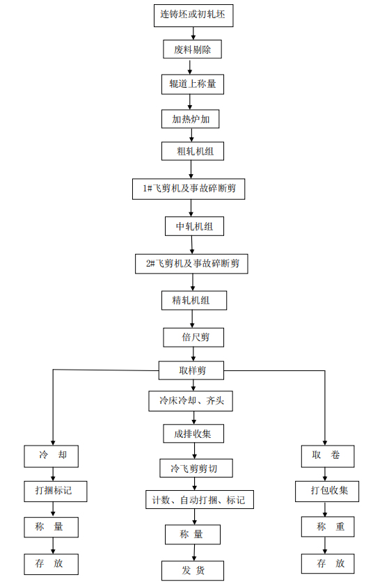
2.3 Heating of blanks
The round steel rolling mill mainly uses the continuous heating furnace, and the side exit method is mostly used. There are two ways to enter the billet: side entry and end entry. The side entry furnace door is small, which is easy to ensure the tightness of the furnace, but it is not as easy to arrange the billets as the end entry. Therefore, both methods use a continuous heating furnace to run the billet in the furnace. The method is divided into push-steel type and step-by-step type. The walking type is further divided into a walking beam furnace, a walking hearth furnace and a walking beam bottom combined furnace. In recent years, most of the square steel rolling mills built by the company use the step-by-step continuous heating furnace, because the step-by-step heating method is more suitable for the production process and product quality requirements of the round steel.
The mechanical equipment in the furnace area includes: charging table, steel separator, rejection device, roller table in front of the furnace, two lifting baffles, weighing device, charging furnace door, charging cantilever roller table in the furnace, alignment pusher, Furnace bottom machinery, discharge furnace door, cantilever roller table for discharge in the furnace, fan, etc.
2.4 Rolling mill and related equipment
1. Rough rolling process and equipment
The main function of rough rolling is to preliminarily compress and extend the billet to obtain a rolled piece with suitable temperature, correct section shape, qualified size, good surface, regular ends and length suitable for process requirements. Rough rolling mills mostly use flat-vertical alternate rolling mills for twist-free rolling, the number of stands generally adopts flat-box-vertical-box, and the average pass extension is 1.28 to 1.32. In the rough rolling stage, micro-tension or low-tension rolling is generally used, because the section size of the rolled piece is large at this time, and it is not sensitive to tension. It is very difficult and uneconomical to set a looper to achieve tension-free rolling. It is necessary to cut the head and tail after rough rolling. The heat dissipation conditions at the head and tail ends of the rolling piece are different from those in the middle part. The temperature at the head and tail ends of the rolling piece is lower, and the plasticity is poor; at the same time, the end of the rolling piece is deformed due to the low temperature, and the deformation is uneven. Causes the irregular shape of the head of the rolled piece, which will cause the entrance guard to block or not bite when continuing to roll. For this purpose, the ends must be cut off after 6 roughing passes. Usually the length of the cut head and tail is 70-200mm.
2. Medium rolling process and equipment
The role of the intermediate rolling is to continue to reduce the section of the rolling stock rolled by the roughing mill, and to provide the finishing mill with the correct section shape, accurate size and uniform size along the entire length of the finished wire rod for the finishing mill. material. The basic functions, operating conditions and process requirements of the intermediate rolling mill are basically the same as those of the rough rolling mill. Therefore, in terms of the type of rolling mill, except that the short center distance compact mill is used in the intermediate rolling mill to meet the specific conditions of rough rolling, the intermediate rolling mill The type of equipment is basically the same as that of the roughing mill. The pass system used in middle rolling is generally ellipse-circle-ellipse-circle pass system. The average pass elongation coefficient of intermediate rolling is generally between 1.28 and 1.34.
3. Finishing rolling process and equipment
The purpose of finishing rolling is to roll out the finished product. In order to ensure the dimensional accuracy of the product and the elongation is small, the elongation coefficients of the finished hole and the front hole of the finished product are generally 1.1 to 1.2 and 1.2 to 1.3. The requirements of finishing rolling on finishing mills are speed and precision. The finishing rolling mill has a large variety of rolling products, complex pass shapes, uneven deformation distribution, and high rolling speed. characteristic
2.5 Shearing equipment and process
There are three rotary flying shears in the rolling process. Among them, the 1# rotary flying shear is placed after the rough rolling unit for cutting head and tail and accident breaking treatment. The 2# rotary flying shear is placed after the intermediate rolling unit, and its function is the same as that of the 1# flying shear. The 3# rotary flying shear is placed after the finishing rolling unit, also called the double-length shear, which doubles the bar before the cooling bed. The ruler section also plays the role of accident breaking. The cold shear is located on the outlet side of the cooling bed and is used to cut the finished steel with fixed length. The cold shear can be divided into two categories according to its cutting method. One is stop shearing, that is, the steel is cut after it is stationary on the roller table; Shearing, that is, the steel is sheared during transportation on the roller table.
2.6 Control cooling process and equipment
The purpose of cooling after rolling of round steel is mainly to obtain the required structure and properties of the product, to make the properties uniform and to reduce the amount of secondary iron oxide scale. In order to reduce the amount of secondary iron scale, it is required to increase the cooling rate. To obtain the required structure and performance, it is necessary to control the cooling process parameters according to different varieties. Generally, the controlled cooling process after rolling of round steel can be divided into three stages. The main purpose of the first stage is to prepare the structure for the phase transformation and reduce the amount of secondary iron oxide scale. Generally, rapid cooling is used to cool to the temperature before the phase transformation, which is called the spinning temperature; the second stage is the phase transformation process, which mainly controls the cooling rate; the third stage is completed, except that the precipitation of solid solution elements is sometimes considered. In addition to slow cooling, air cooling is generally used.
2.7 Equipment and process of cooling bed area
The cooling bed area equipment includes cooling bed inlet equipment, cooling bed, cooling bed outlet equipment, etc.
The cooling bed inlet equipment includes input roller table, overlapping device, lifting skirt roller table, steel separator, safety baffle, etc.
The cooling bed cools the rolling stock in air and transports the rolling stock to the cold shear work area. In order to ensure that the slender rolled pieces with small cross-section and long length will not be bent and twisted due to the cooling process, and to prevent the surface of the rolled piece from being scratched, the round products generally use a stepping rack type cooling bed and a pendulum cooling bed. . The cooling bed consists of a cooling bed body, an alignment roller table, a fixed baffle and a water cooling system.
The cooling bed outlet equipment includes a roller table with a bar layer conveying trolley and a bar layer forming device.
2.8 Finishing, transportation and finished product storage of round steel
(1) Trimming of the round bar The trimming of the round bar is mainly to trim its head and tail. Relatively speaking, the head and tail of the round steel are prone to defects, and the width of the rolled piece at the head and tail is too large, which is easy to cause the size to exceed tolerance. For this reason, the round steel should be trimmed before bundling, and the defects at the head and tail of the round steel should be cut off.
(2) Finished product inspection The round steel product inspection includes the appearance quality inspection and the organization performance inspection of the round steel. The organization performance inspection is carried out in accordance with the national or enterprise standard regulations and the technical requirements put forward by the user in the contract. External quality inspection is to check whether the shape, size and surface defects of round steel meet the standard requirements
2.9 The process of the baler
The automatic baler has been developed in recent years to improve the operation rate and reduce the labor intensity. It replaces the traditional manual manual packing or manual simple pneumatic packing on the continuous rolling mill. Generally, automatic balers are divided into wire automatic balers, bar automatic balers, section steel automatic balers, etc. according to different products.
Hole design
3.1 Determining the elongation coefficient of each pass
Product requirements: Rolled from 140×140mm billet to round steel with diameter of 20mm
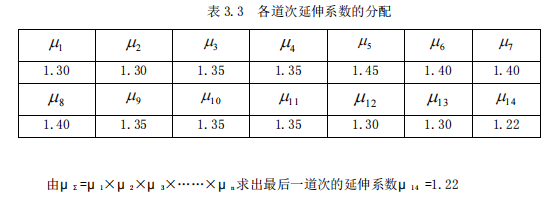
(1) Calculate the total elongation coefficient
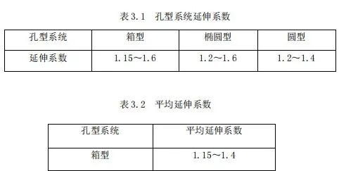
According to the layout of the rolling mill and the selected pass system, referring to the relevant elongation coefficient and taking the average elongation coefficient μ = 1.35, the number of rolling passes is:
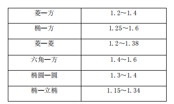
Selection of pass system: The round steel pass system is generally composed of two parts: the extended pass system and the finishing pass system. The function of the extended pass system is to compress the section of the rolled piece and provide a suitable red blank for the finished pass system. It has a great influence on the output and quality of steel rolling, but has little effect on the shape and size of the product. Commonly used extended pass systems are box-shaped, diamond-rhombus, diamond-square, ellipse-square, ellipse-circle, hexagonal-square, ellipse-elliptical, etc. The commonly used finishing pass systems are square-ellipse-circle, circle - Ellipse - Circle etc.
The whole pass system is divided into three parts: rough rolling, intermediate rolling and finishing rolling
Rough rolling pass system: The cross section is large, the box pass system is used to solve the problem of blooming head, and it is beneficial to remove the primary iron oxide scale formed on the surface during heating.
Medium rolling pass system: elliptical-square, hexagonal-square and other pass systems can be used, and the use of ellipse-circular pass system is conducive to automatic recognition of the surface of the rolled piece and feeding steel, and the deformation is stable
Finishing rolling pass system: The ellipse-circular pass system is adopted, because although the elongation coefficient is small, the deformation relaxation can ensure the product quality, and the rolling mill is alternately arranged horizontally and vertically, which is conducive to the realization of turning steel.
The selection of hole pattern system is: 1 rectangular box-2 square box-3 rectangular box-4 square box-5 ellipse-6 circle-7 ellipse-8 circle-9 ellipse-10 circle-11 ellipse-12 circle-13 ellipse- 14 round
(2) Distribution extension factor:
3.2 Determining the section size of each pass rolling
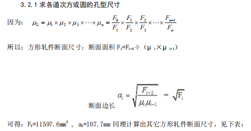
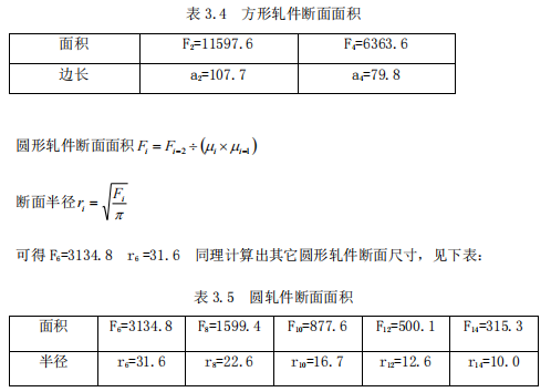
3.2.1 Find the hole size of each pass or circle
3.2.2 Determine the size of the intermediate rolling stock of the pass system
The intermediate rolling piece refers to the rolling piece between the front and rear square (round) pieces, which can be rectangle, diamond, hexagon, ellipse, etc., and the section size of the intermediate rolling piece refers to the height and width.
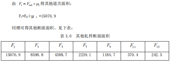
Calculate the size of the rolled piece according to the clip ellipse
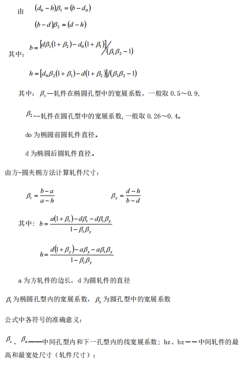
bA, hA, ba, ha——the dimensions of the height and width of the square piece in the pass, which is the size of the rolled piece, and the dimension of the non-pass, which can be 1.2 times the length of the side. When the middle hole is a rhombus, in order to simplify the calculation, the dimensions at the sharp corners shall prevail. In this way, hz, bz, bA, hA, ba, and ha are all diagonal dimensions.
Generally, the expansion coefficient is selected according to the following table:
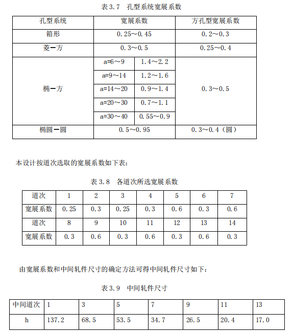

3.3 Pass Design Calculation
3.3.1 Design of finishing pass
1. Finished hole design
The round bar finished pass is the quality of the round steel pass design, which directly affects the dimensional accuracy of the finished product, the adjustment of the rolling mill and the life of the pass. When designing the pass shape of the round steel, generally it should be considered that the ovality change is small, and the allowable deviation range can be fully utilized, that is, the adjustment range can be ensured. In order to reduce overfilling and facilitate adjustment, the shape of the round steel finished pass adopts a circular hole with expansion angle.
At present, there are two widely used methods for forming finished holes, one is the double-radius arc method, and the other is the expansion angle method in which the two sides of the hole are connected by tangent lines. The double-radius arc method has long been a common design method for round steel finished holes, but with the improvement of the quality requirements for round steel products, this method is not suitable for the production of high-precision round steel, because the design of this finished hole causes tolerances The belt is reduced, the adjustment range is narrowed, and the finished size is difficult to control.
The advantages of the expansion angle method connected by tangent lines on both sides of the hole pattern are:
1. The drawing is simple, and it is easy to make the rolling groove model;
2. The center opening angle is relatively small, which improves the roundness of the rolled piece, and the parts where the metal exceeds the standard circle during rolling are relatively small;
3. The pressure measuring function is increased, which strengthens the function of restricting the width of the rolling stock, and is more conducive to controlling the size of the finished product in the width direction;
4. When the rolling piece is full of pass, the diameter of the roll gap slash will still not exceed the tolerance range;
5. It can reduce the phenomenon that the diameter exceeds the tolerance range on the circumference corresponding to the center angle of 30° after the hole pattern is worn. Therefore, the expansion angle method in which the two sides of the hole are connected by tangents is adopted in this design. The height hk of the finished hole pattern is:

d is the nominal diameter of the round steel or the standard diameter, in mm; Δ _ is the negative tolerance, in mm; 1.007~1.02 is the thermal expansion coefficient, and its specific value is determined according to the final rolling temperature and steel grade, and various steels can be taken as :
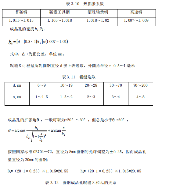

Take the roll gap from the above table s=2mm
Then θ = 19.4°
Outer circle radius: r=1mm The hole pattern is as follows:
2. The composition of the front hole of the finished round steel
The front hole of the elliptical finished product is an elliptical hole type, and the front circular hole of the finished product is determined by the calculation method of the absolute expansion coefficient.
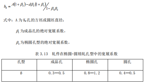
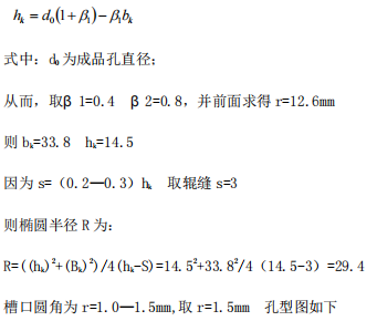
3. Round steel finished product and then front hole
The round-ellipse-circle finishing pass system finished product and the front hole is a round hole.
Diameter of base circle:
When the diameter of the round steel is d0=8—12, D3=H3=(1.18—1.22) d0
When the diameter of the round steel is d0=13—30, D3= H3=(1.21—1.26) d0
In the formula: d0 is the diameter of the finished round steel;
Hole width: bk=(1.15—1.28) D3
Thus: D3= H3= (1.21-1.26) d0= 25
bk=(1.15—1.28) D3= 30
Take roll gap s =2mm
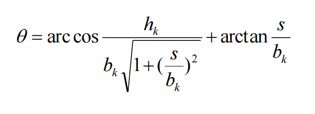
Then θ = 37.6°3.3.2
Extended hole design
1. The composition of the box hole
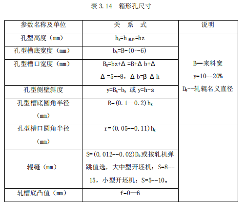
2. The composition table of the oval hole
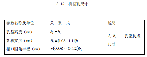

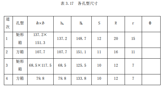
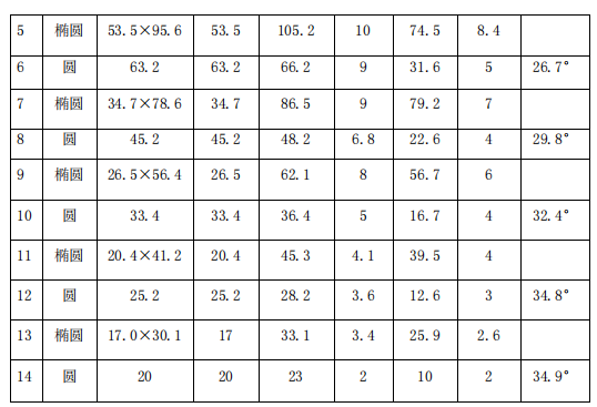
Bring the data into the corresponding tables above, and obtain the hole size of each extension hole as:
Chapter 4 Checking
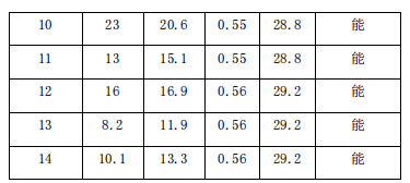
4.1 Biting check
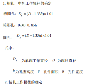
2. Determination of finish rolling work roll diameter
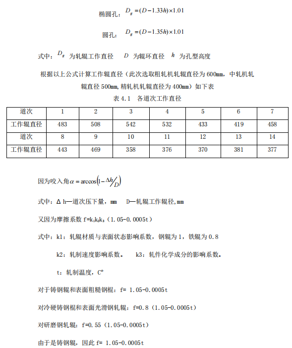
Because the S·Eklund formula is used in the following range: the temperature of the rolling stock is greater than or equal to 800°C, the material of the rolling stock is carbon steel (the chemical composition of Mn does not exceed 1% and the Cr does not exceed 2-3%), and the rolling speed does not exceed 20m /s.
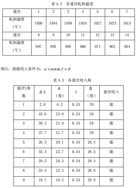
Due to the process characteristics of high-wire rolling, the temperature during rolling is difficult to calculate with formulas. Therefore, the data collected in the actual production of similar workshops are used to roughly determine the temperature of each pass. See the table below for details.
4.2 Roll check
When the pass design of a new product is completed, or the technical transformation of the rolling mill is carried out, the strength of the roll must be checked to determine the rationality of the process specification design.
According to the previous roll matching situation, the rolls of each rolling mill have multiple rolling grooves. When each rolling groove passes through the steel, the rolling pressure and rolling torque are the same, and according to the relevant knowledge of material mechanics: when the intermediate rolling When the channel passes through the steel, the bending moment of the dangerous surface of the roll is large, and the roll is dangerous. In the production of section steel, the rolling force on the roll is usually regarded as a concentrated force.
4.2.1 Calculation of rolling pressure
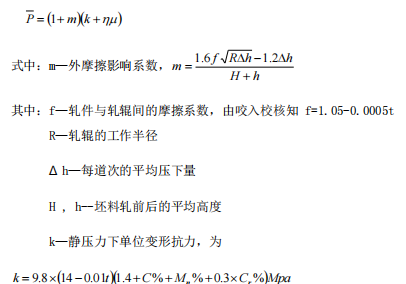
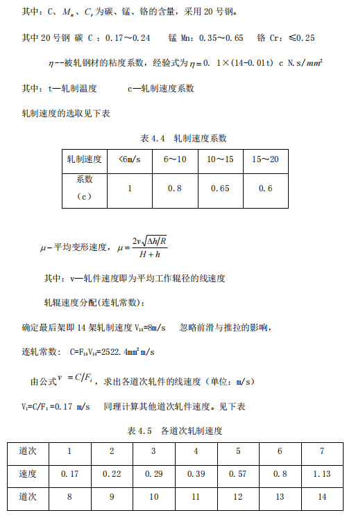
1. Calculate the unit rolling pressure, using the Eklund formula

2. Calculate the contact area
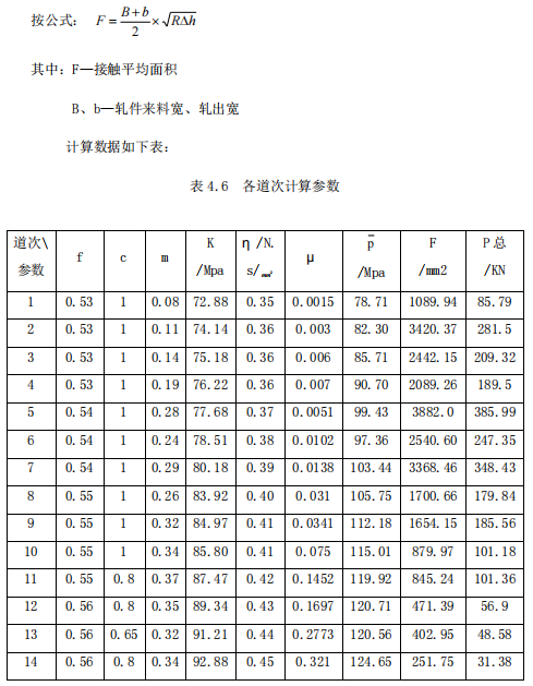
4.2.2 Calculation of rolling force
There are three ways to control the torque:
1. Calculate the rolling moment according to the total pressure P of the metal acting on the roll.
2. Calculate the rolling torque according to the tangential friction force of the metal acting on the roll.
3. Determine the rolling torque according to the energy consumption during rolling.
A method is used in the calculation.

In the formula: P—rolling pressure
x—arm coefficient, for Φ 20mm round steel production, take x=0.5
R—the radius of the work roll diameter
Δ h—reduction amount
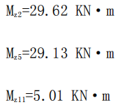
Bring in the data:
4.2.3 Roll check
The rolls directly bear the rolling force and the rotational moment of the rotating rolls. Therefore, the strength of the rolls often determines the load capacity of the entire rolling mill. In order to ensure that the rolls have sufficient strength to resist damage, the strength of the rolls is generally checked after the pass design is completed. Including: check of roll body strength, roll neck strength and roll head strength. Usually, the bending is calculated for the roll body, the bending and torsion are calculated for the roll neck, and the torsion is calculated for the transmission end. The rolls of the section steel rolling mill are arranged with many pass grooves along the length of the roll body. The rolling pressure can be approximately regarded as the concentrated force. When the rolling stock is rolled in different rolling grooves, the action point of the rolling force is changed. Therefore, it is necessary to judge the stress of each section of the roll when different rolling grooves pass through the steel, compare them, and find out the dangerous section.
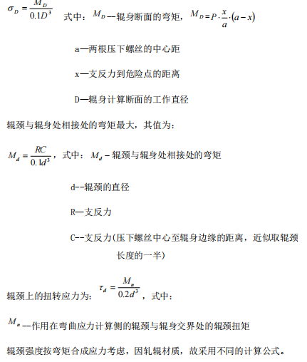
The bending stress of the roll section is:
1. When using steel rolls, according to the fourth strength theory:

2. When using cast iron rolls, Moore's theory:
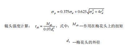
In the production of section steel, the rolling force on the roll is usually regarded as a concentrated force.
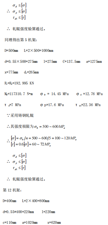
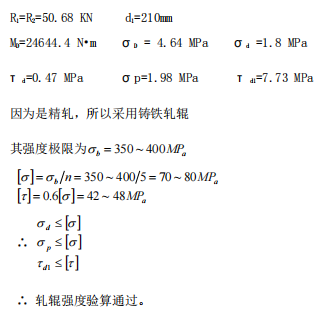
Because the rolling force applied to the rolling stock by the rolls of the 2nd stand of rough rolling, the rolls of the 5th stand of intermediate rolling, and the rolls of the 11th stand of finishing rolling is large, so the three rolls are dangerous, so they are checked.
Rack 2:
Roll body length L of section steel mill/roll body diameter D=1.5—2.5, take 2
Since D=600mm
So the length of the roller body L=2×600=1200mm
Choose rolling bearings
Roller diameter d=(0.50~55) D C=l/2d take d=0.55D=0.55×600=330
Then l=1*330=330mm C=330/2=165mm a=L+2C=1530mm
Using plum blossom shaft head
Then d1=d-10=320mm (outer diameter of plum blossom shaft head)
x=930mm
(1) From statics, the support reaction force at the roll neck of the roll is obtained as:

(2) The bending moment at the roller body is:


(3)Roller body strength calculation:

(4)Roll neck strength:

(5)Torsional stress at the critical section of the roll neck (ignoring the friction moment, then Mn=Mz=29620N.m)
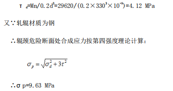
(6)Calculation of roller head strength (using plum blossom roller head)

(7)The force of the roll is:

